A real 64-key keyboard for Otterchip, measured.
The current deck shows a made-up 14.5-unit keyboard at 17.6 mm pitch. This study picks a purchasable GK64-layout plate-and-PCB, models it from open CAD, manufacturer drawings and photo measurements, and shows what the Model M deck must change to hold it. Provisional — pending the owner’s donor choice. Nothing has been purchased or bench-measured.
Recommendation
YMDK DK61-64 hot-swap PCB + YMDK 60% Plate A (2u shift)
DK61-64 PCB, variant “2u Shift 64 ANSI ISO” (SKU YMDK-shopify-5270, $38.50, in stock) with the 60% aluminium plate, Plate A “2u shift” (YMDK-shopify-0100/0101/0099, $18.90, in stock), plus PCB screw-in stabilisers (1 × 6.25u, 3 × 2u), 64 MX-style switches and MX keycaps.
YMDK GK64x wired PCB + FR4 plate + plate stabs
One SKU (YMDK-shopify-1499, $65.90, in stock). Same GK64 layout and GH60 outline; its photos fit the GH60 holes within 0.5 mm, and the listing documents three plate-to-PCB screws. Trade-offs: remapping needs the proprietary GK6X Windows/macOS driver, it has per-key RGB, a microphone under the space bar, and plate-mount stabilisers only.
Also checked: Keychron K7 Max (low-profile, manufacturer CAD) — unavailable on keychron.com today, proprietary low-profile caps, licence restricts redistribution of derived CAD. KBDfans DZ60RGB V2 — 63 keys, out of stock.
Component model
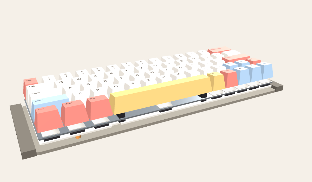
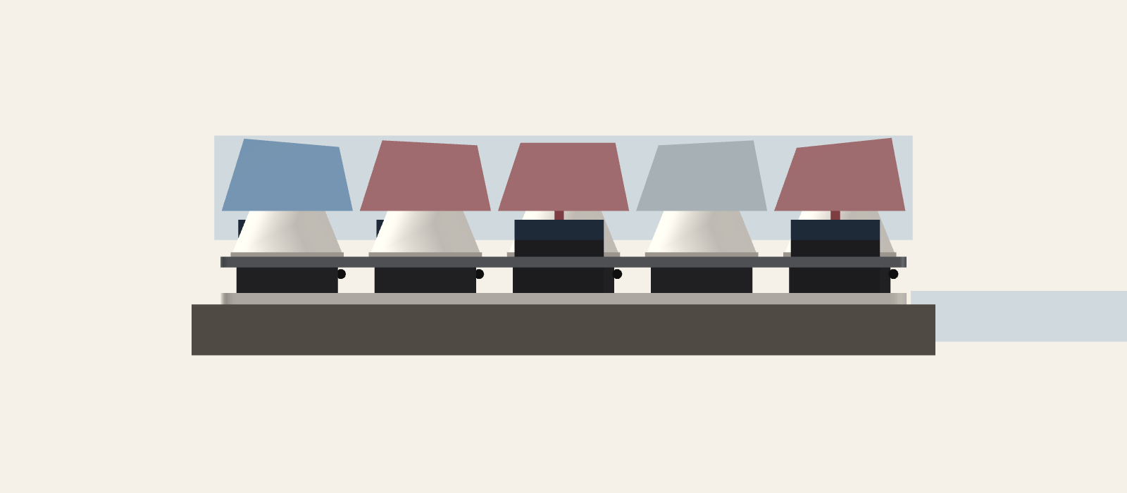
web/otterchip-component-typing.js defines buildOtterchipTypingKeyboard(THREE, options), OTTERCHIP_TYPING_DATA and otterchipTypingOriginForDeck(deckY, deckAbovePlate). Frame: x right, y up, z toward the user; origin at the PCB-footprint centre with y = 0 at the underside of the proposed bed. Toggling parts or profiles rebuilds the model without moving the camera.
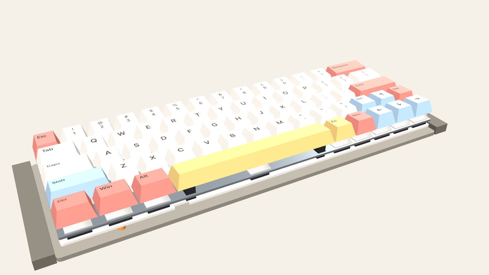
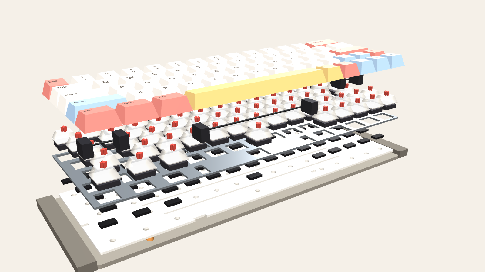
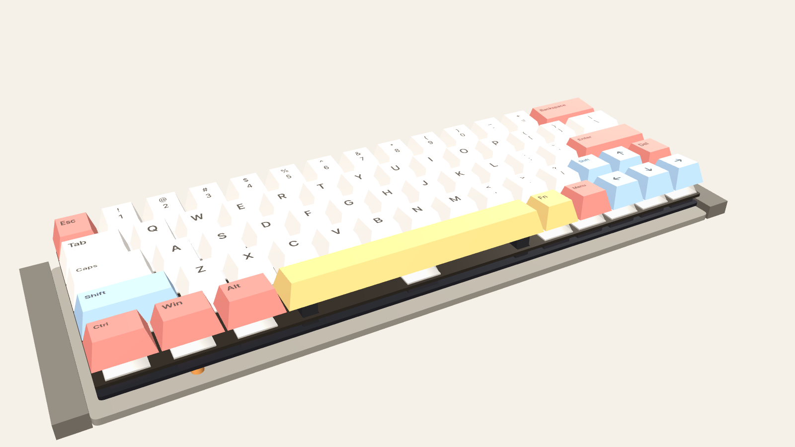
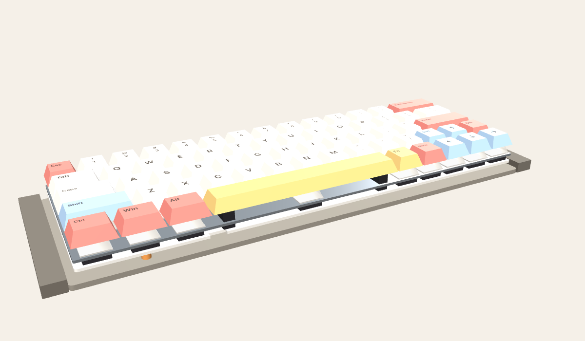
Key data for the emulator
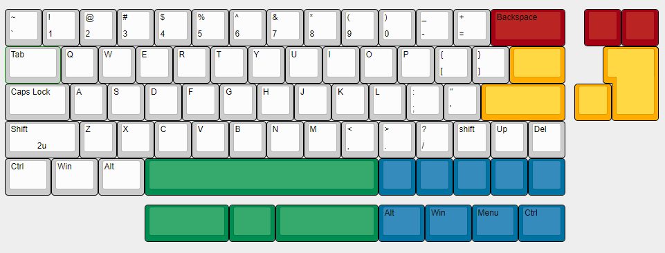
Each of the 64 keys has a legend, shifted legend, KeyboardEvent.code, colour role, unit width, row, centre (mm) and stabiliser spacing, so the main emulator can apply shared palettes by role (). Key groups carry userData.code, baseY and travel (4 mm) for press animation; userData.otterchipTyping.keyMeshes uses the existing CODE:… naming.
Dimensions and where they come from
documentedmanufacturer drawing or datasheet · CADopen-source PCB file · photomeasured from product photos · assumedengineering estimate · proposalthis study
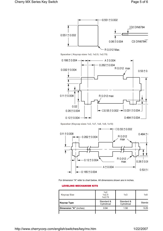
CAD inspection: the open GH60 board
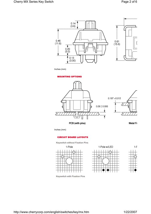
The komar007 GH60 KiCad board (rev B, commit e7948cf) was parsed directly (scripts/parse_gh60.py). It provides the 60% outline, the tray-mount hole pattern that GH60-compatible cases and PCBs share, stabiliser footprints, and the USB position. YMDK’s cases list GK64 and DK-series boards as GH60-compatible. The photographs below test that claim for the specific boards.
Photo matching and measured residuals
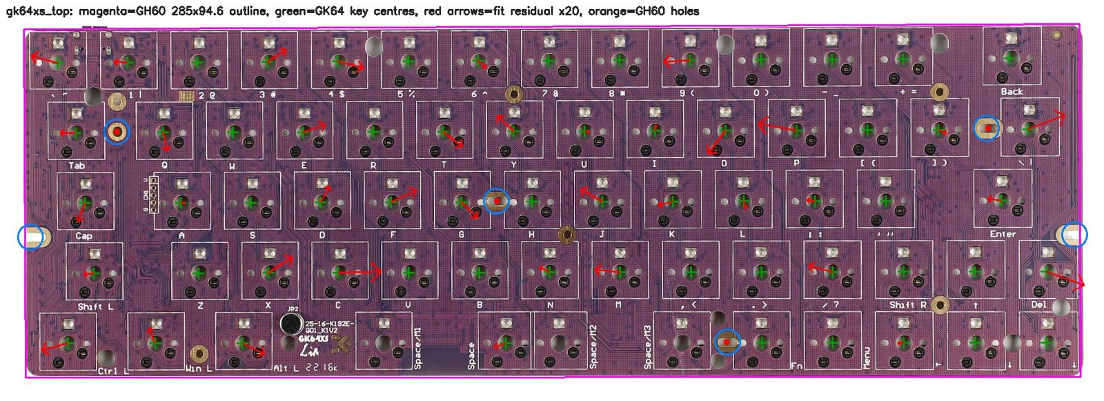
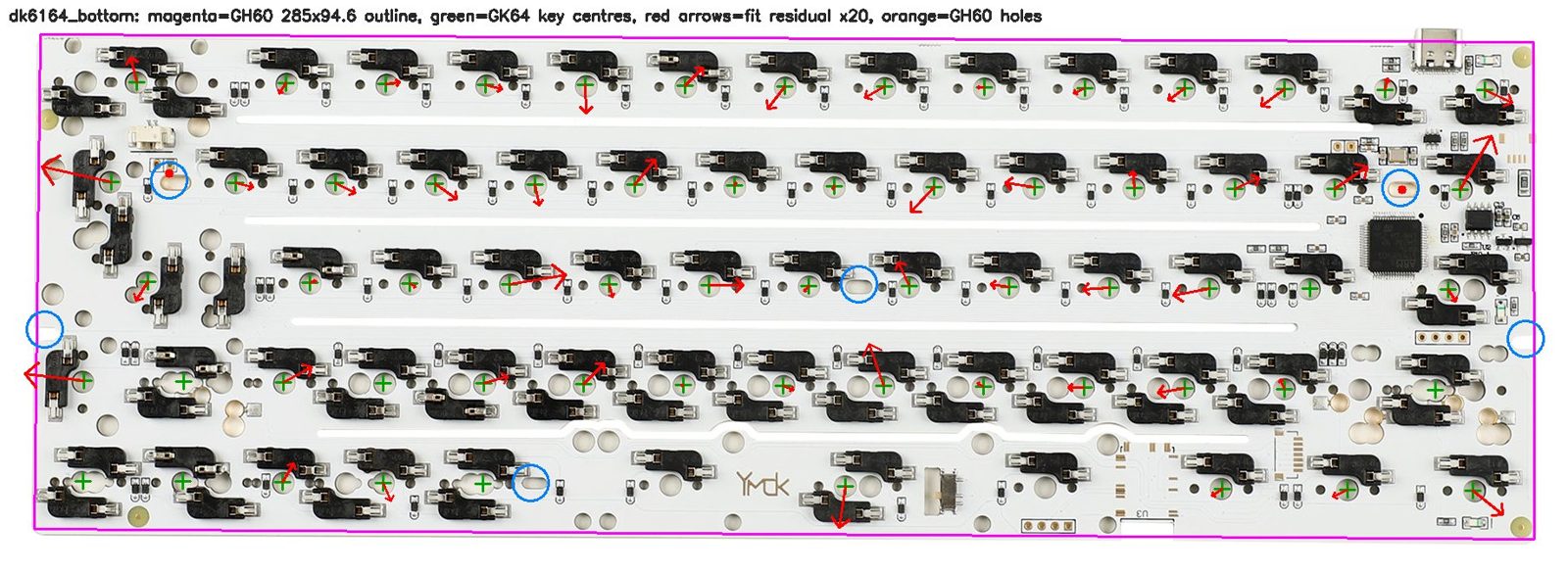
No YMDK drawings exist. Each near-orthographic or oblique product photo was mapped to the GH60/GK64 millimetre grid with a least-squares planar homography. The fit uses detected switch-centre holes (PCBs) or 14 mm cut-outs (plates). Residuals are back-projected into millimetres and reported with leave-one-out RMS values. These are single uncalibrated photos, so lens distortion and board flatness limit accuracy to roughly ±0.3–0.7 mm, not the KiCad tolerance.
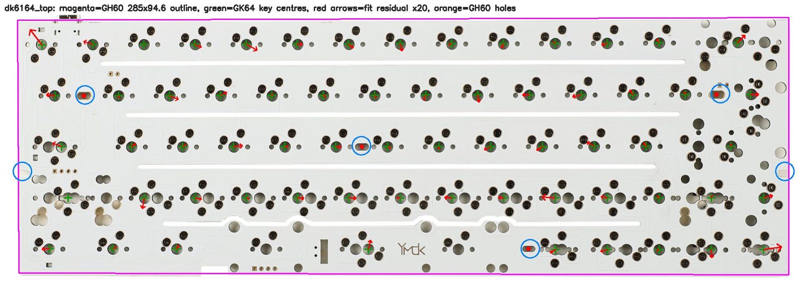
Rectified 12 mm windows at each GH60 hole (top row DK61-64, bottom row GK64XS), centred on the nominal KiCad position. The DK61-64 H1 and H4 slots appear 0.5 and 1.3 mm left of nominal. The board may differ there, or the result may be photo error near the edge. Treat both holes as ±1.5 mm in x until a board is in hand.
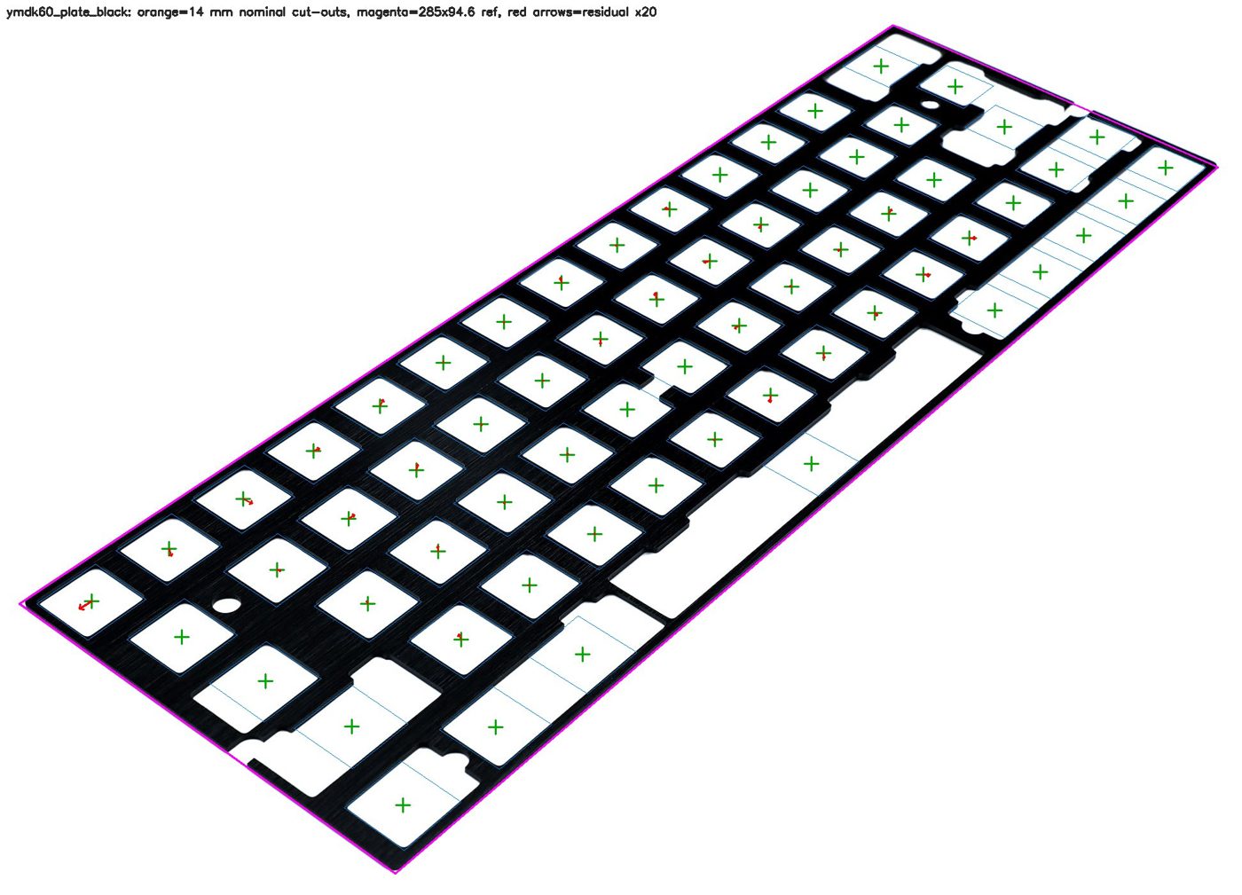
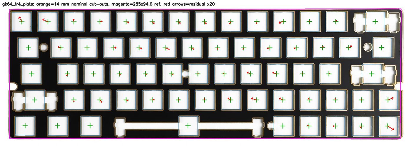
Vertical stack and the deck
A generous, serviceable support bed
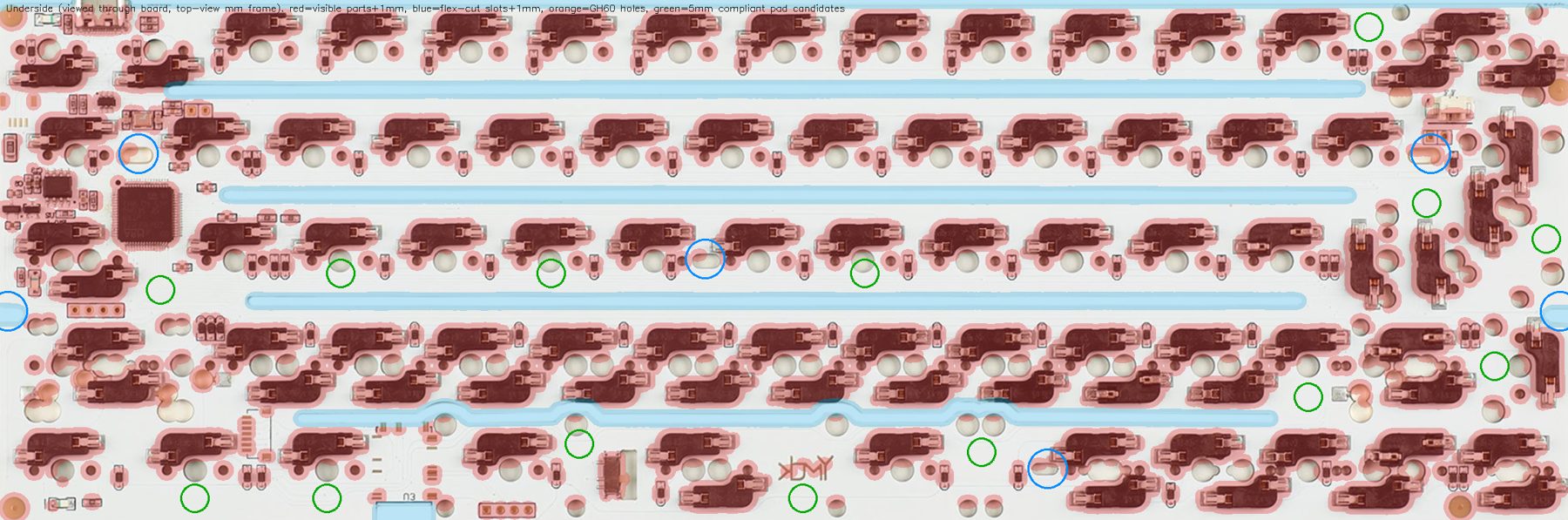
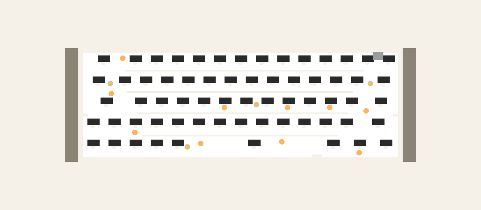
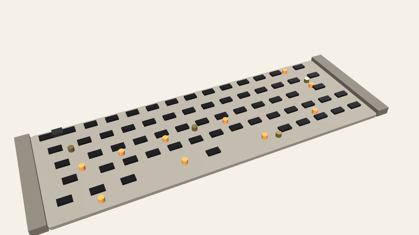
Envelope versus the current visual, and required deck changes
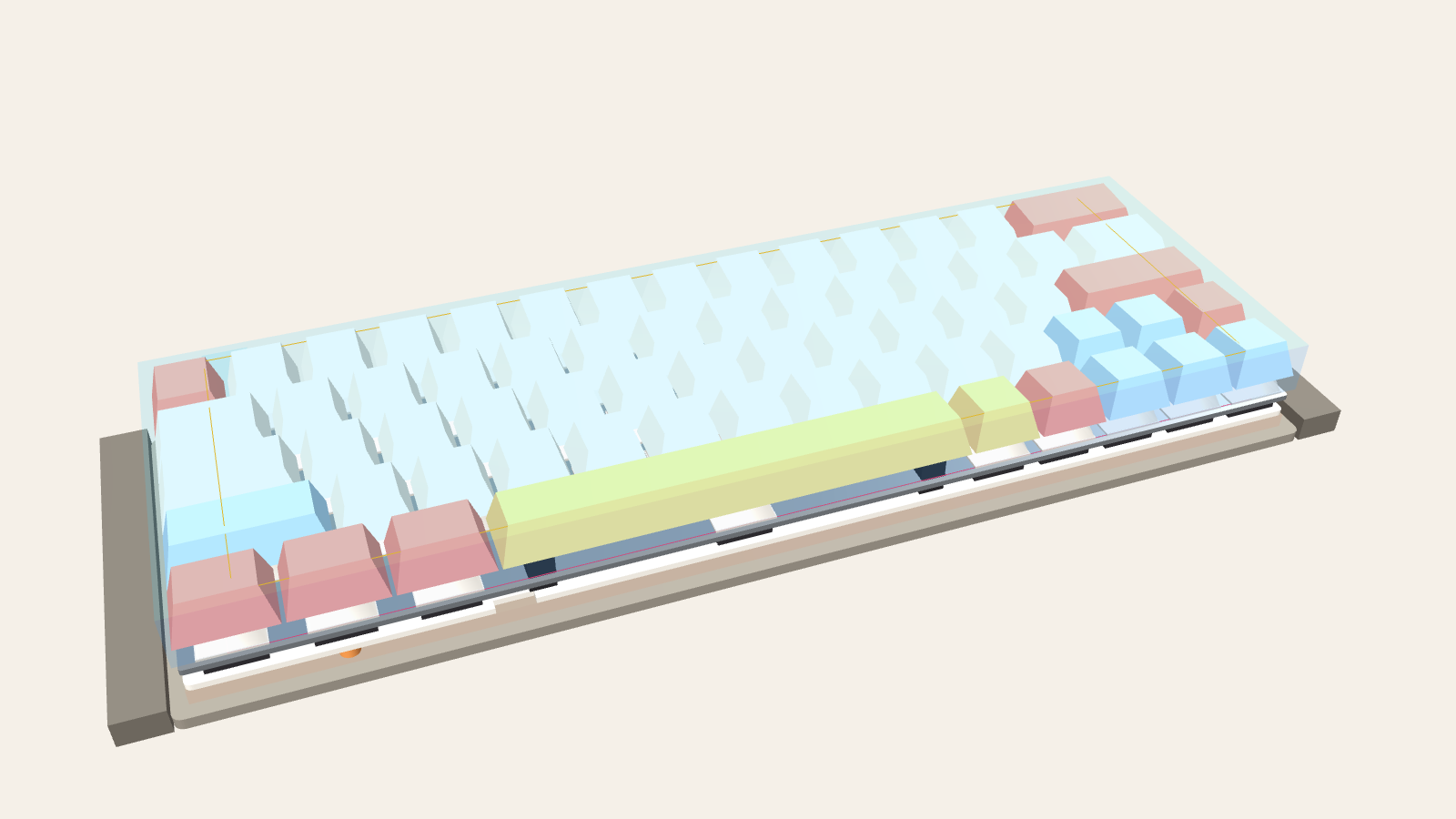
SE25 underlap: vertical gap options
Changes the parent model needs
Exports and reuse
OBJ/MTL and GLB files were generated from the live component (mm; the GLB root node scales to metres). Legend textures are not embedded. Source data: typing_report.json.
Still unknown
Sources (accessed 2026-11-05)
Reproduce
YMDK product photographs are reproduced at reduced size only as measurement evidence. Keychron CAD was consulted, but none was imported.